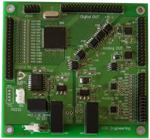
Multifunctional Data Multiplexing Controller (DMX)
DMX is very simple to install and use. It is robust in operation. Download Specification.

DMX area of application:
- vehicle control systems (ROV, RC boat, AUV)
- operator console (joysticks console)
- data acquisition subsystem
It is designed to work in several modes:
- DMX – DMX (no PC required). It is popular and simple scheme when one controller installed inside of operator’s console or remore control, and another – on remote site in your device. When user (operator) changes values input ports on one controller than same values appears on output ports of another controller. DMXs linked to each other by 3-wire serial RS-232 asynchronous interface. Serial line can be transferred over any media: 3-wire null modem cable, Ethernet and Wi-Fi (using Ethernet/Wi-Fi to serial converter) or fiber optic (using Serial to fiber converter or another digital multiplexing device).
- Computer – DMX. This option is useful when your computer controls devices connected to Controller DMX by sending Events triggering commands, gather and record data from controller analog and digital ports (Data logging system).
- DMX – Computer – DMX. In this mode Computer will translate operator control commands to another DMX controller or controllers in the system. For example one controller installed in console, another – in data acquisition module and last one in vehicle motion control module. In other way vehicle controller may send its digital and analog ports states to console through Computer for indication purposes. Amount of controllers connected to single computer is limited by this computer characteristics only.
Controller DMX board designed in PC-104 form-factor format. Please note, that it is not compatible to PC-104 ISA/PCI buses.
Controller DMX general characteristics
Opto-isolated analog and digital buses
Independent Ground for Digital, Analog, Data and Power lines
Serial interface settings, RS-232: 38400/8/n/1. TTL: by request
Data refresh rate: 20 Hz
Digital Input: 30 channels (TTL)
Digital Output: 30 channels (TTL)
A/D resolution: 16 bit
Analog Input (0-5V) single-ended: 16 channels
Analog Output (0-5V) single-ended: 16 channels
Input impedance: 5 GΩ
Input voltage: 24 VDC ±10%
DMX board dimensions (W x L x H) PC-104 format, mm: 90 x 96 x 12 (other form-factor by request)
Operating temperature: -45 ÷ +75 ⁰C
Download Specification.
Bi-directional Controller DMX data protocol
Data protocol utilizes for communicating Controllers between themselves and/or between computer and controllers. Controller DMX test tool uses this data protocol also.
The protocol is bi-directional. That means that each side sends states of its Input ports and switches states of its Output ports according to incoming data string.
- Data string format: ASCII NMEA 0183 style, unique header, HEX data blocks delimited by ‘comma’, Check Sum, Carrier Return and Line Feed symbols;
- Data update: Data refresh (update) rate: 20 Hz;
- Serial Port settings: RS-232, asynchronous, 38400 bit/s, 8 bit, no parity, 1 stop bit.
Data format of Analog Input ports (AI) values
AI#0 – AI#15: 4 bytes for every AI port. Elder symbol with a lower address.
Data sends in ASCII symbols, Values are in range 0x0000 — 0xFFFF (4 digits HEX number)
Data format of Digital Input ports (DI) values
DI#3 – DI#0 2 bytes per DI port. Elder symbol with a lower address.
Data sends in ASCII symbols, Values are in range 0x00 — 0xFF (2 digits HEX number).
Significant bits in a byte are presented right to left: least significant bit is 1, most significant bit is 128
Control Sum
2 bytes reserved for Check sum. Data sends in ASCII HEX symbols. Elder symbol with a lower address.
Formula: the sum modulo 2 (“exclusive or” operation) of bytes from address #1 to #97 included
Delimiter
Data blocks delimiter in the string: ASCII code of ‘comma’ symbol
End of string symbols
End of string: 2 HEX symbols used – CR and LF (0X0D and 0X0A)
Full description of Controller DMX data protocol you may download here.
To get a quote – send an inquiry.
